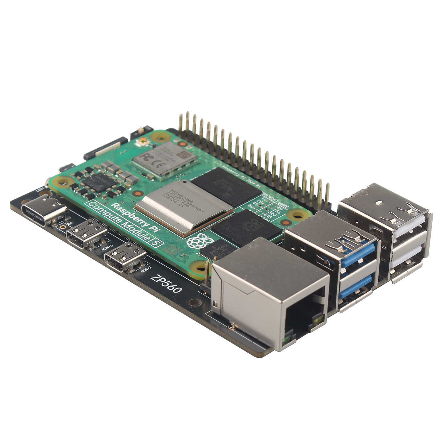
ZP560 CM5 IO Board
|
||
Overview
The ZP560 IO board is compatible with the size and functions of Raspberry Pi 5. There are many Raspberry Pi 5 peripheral accessories, but CM5 peripheral accessories are less. For some customers who like CM5, after using the ZP560 IO board to install CM5, you can use Raspberry Pi 5 peripheral accessories, such as M.2 HAT, PCIe HAT, NVMe HAT, PoE+/PoE HAT, WiFi HAT, Ethernet HAT, AI HAT, etc. It’s also perfectly compatible with Raspberry Pi 5 case, which brings great convenience to CM5 customers.
Features
• IO Carrier board for Raspberry Pi Compute Module 5 Lite/eMMC series module, with onboard CM5 socket, Gigabit Ethernet RJ45 port, PCIe 16PIN Interface, 40PIN GPIO header, USB 3.2 Gen1 × 2, USB 2.0 × 2, 4-lane MIPI interface × 2, Micro HDMI port × 2, PoE 4PIN header, TF card slot, Fan Header, etc.
• We can use Type C as a USB SLAVE interface to flash images. Note not to connect other devices when using Type C for flashing. Please use high quality power supply, power supply with a lower output voltage for flashing will cause the device to be unrecognized.
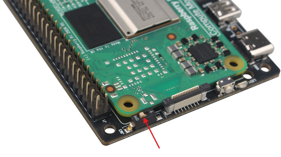
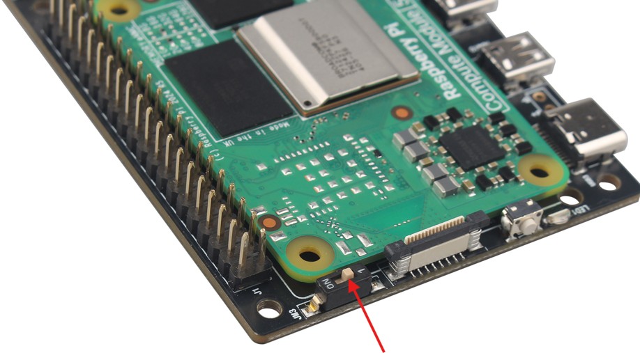
• Onboard BOOT switch, switch the BOOT switch to ON and connect to the computer through Type C to let the device enter the flashing mode; switch the BOOT switch to 1 to enter the normal mode.

Compatibility
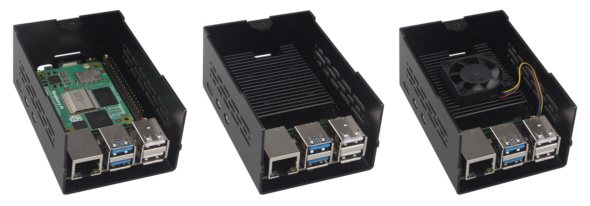
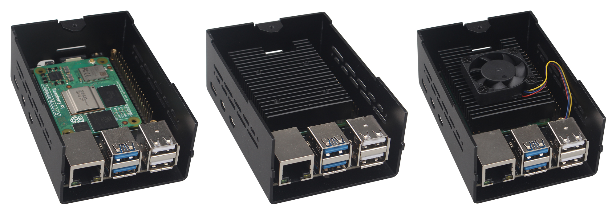
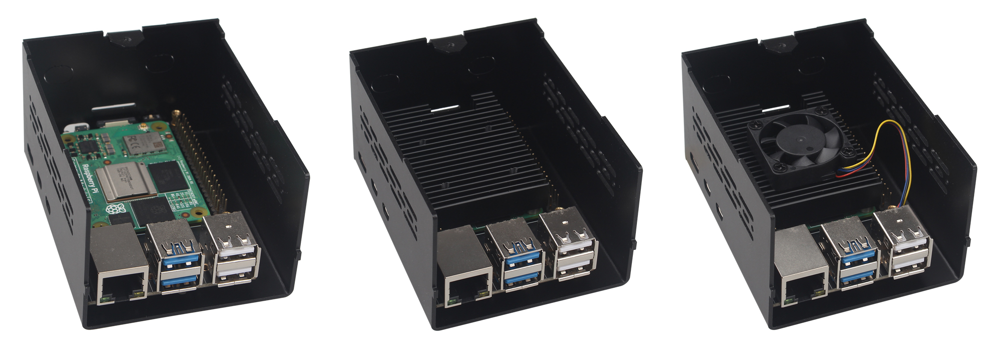
The ZP560 IO board is compatible with our Aluminum Case, NVMe HAT, PoE+ HAT, WiFi HAT, Ethernet HAT, and Heatsink.
• Aluminum Case:
ZC501 (ASIN: B0DSZYLMSS):
ZC502 (ASIN: B0F2995JCY):
ZC506 (ASIN: B0F93SQ67G):
• NVMe HAT: ZP511 (ASIN: B0CZ6NWXYL), ZP515 (ASIN: B0CYWFGKDB), ZP517A (ASIN: B0D1QYDJJJ), ZP518 (ASIN: B0F2974W33), ZP519 (ASIN: B0F299Y72Y).

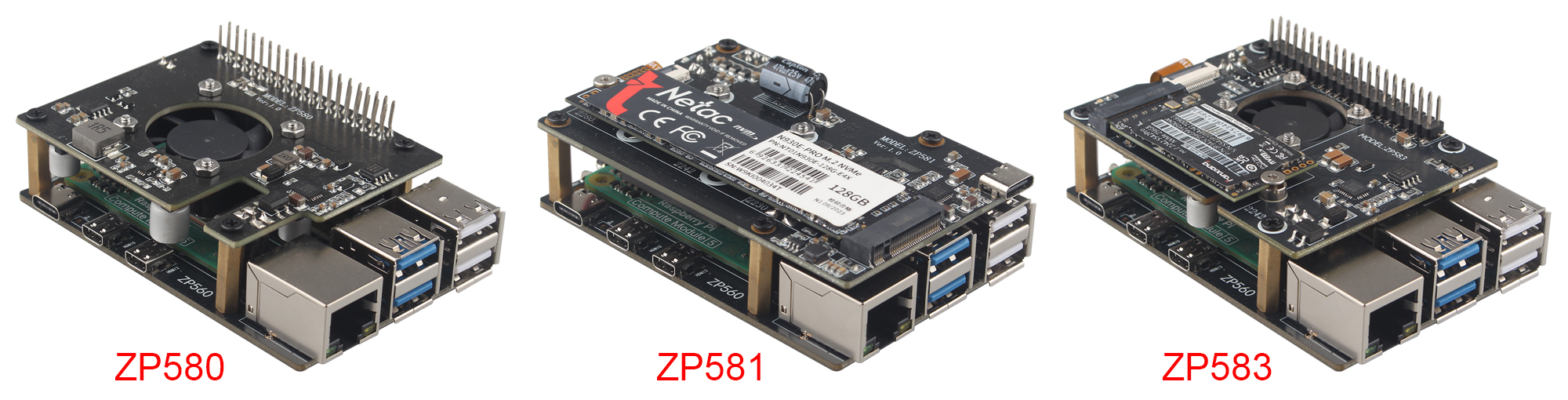
• PoE+ HAT: ZP580 (ASIN: B0D7VTH1HX), ZP581 (ASIN: B0DNJDMW7V), ZP583 (ASIN: B0DYDR89GC).
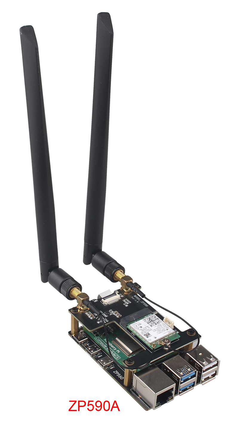
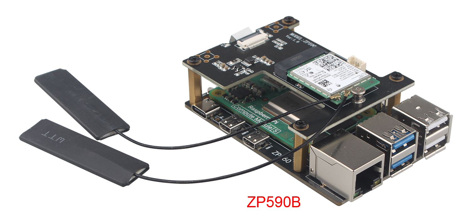
• WiFi HAT: ZP590A (ASIN: B0D78TWCB9), ZP590B (ASIN: B0D78V96R4).
• Ethernet HAT: ZP591 (ASIN: B0FDGMQS95), ZP593 (ASIN: B0DQ8C1PBD), ZP595 (ASIN: B0DQ8BLD6L), ZP596 (ASIN: B0FHW9FXT2), ZP597 (ASIN: B0FHWCBF7F) , ZP598 (ASIN: B0FQ1F1YSQ).

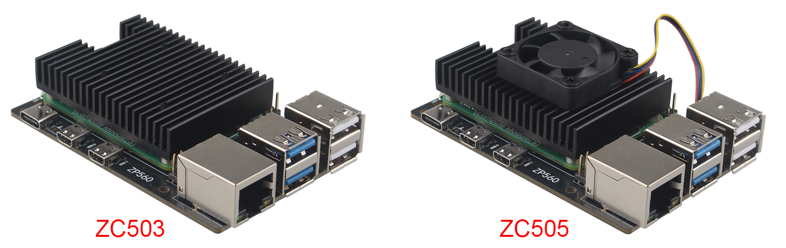
• Heatsink: ZC503 (ASIN: B0DSZRWCCK), ZC505 (ASIN: B0DT12D9F3).
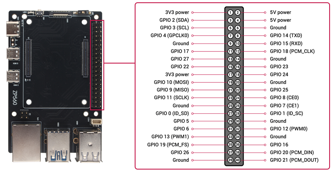
GPIO and the 40-pin header
The GPIO headers on all boards have a 0.1in (2.54mm) pin pitch.
Connector for PCIe
To connect a PCIe HAT+ device, connect it to ZP560, Your ZP560 should automatically detect the device. To connect a non-HAT+ device, connect it to your ZP560, then manually enable PCIe.
Enable PCIe
By default, the PCIe connector is not enabled unless connected to a HAT+ device. To enable the connector, add the following line to /boot/firmware/config.txt:
dtparam=pciex1
Reboot with sudo reboot for the configuration changes to take effect.
Boot from PCIe
By default, ZP560 devices do not boot from PCIe storage. To enable boot from PCIe, change the BOOT_ORDER in the bootloader configuration. Edit the EEPROM configuration with the following command:
sudo rpi-eeprom-config --edit
Replace the BOOT_ORDER line with the following line:
BOOT_ORDER=0xf416
To boot from a non-HAT+ device, also add the following line:
PCIE_PROBE=1
After saving your changes, reboot your CM5 with sudo reboot to update the EEPROM.
PCIe Gen 3.0
To enable PCIe Gen 3.0 speeds, add the following line to /boot/firmware/config.txt:
dtparam=pciex1_gen=3
Reboot your ZP560 with sudo reboot for these settings to take effect.
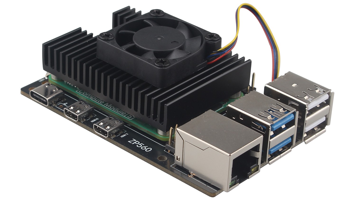
Fans
Both of the ZP560 options plug into the four-pin JST-SH PWM fan connector located in the upper right of the board between the 40-pin GPIO header and the USB 2 ports. The fan connector pulls from the same current limit as USB peripherals. We recommend the Active Cooler case for overclockers, since it provides better cooling performance.
As the temperature of the CM5 increases, the fan reacts in the following way:
• below 50°C, the fan does not spin at all (0% speed)
• at 50°C, the fan turns on at a low speed (30% speed)
• at 60°C, the fan speed increases to a medium speed (50% speed)
• at 67.5°C, the fan speed increases to a high speed (70% speed)
• at 75°C the fan increases to full speed (100% speed)
Temperature decreases use the same mapping with a 5°C hysteresis; fan speed decreases when the temperature drops to 5°C below each of the above thresholds.
You can use our ZC505 heatsink which is equipped with cooling fan, please see the following picture:
Fan connector pinout
The ZP560 fan connector is a 1mm pitch JST-SH socket containing the following four pins:
| Pin | Function | Wire colour |
| 1 | +5V | Red |
| 2 | PWM | Blue |
| 3 | GND | Black |
| 4 | Tach | Yellow |
Power over Ethernet (PoE) connector
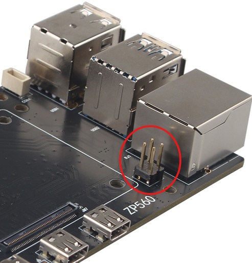
The Ethernet jack on ZP560 is PoE+ capable, supporting the IEEE 802.3af/at PoE standard.
Power button
When you plug your ZP560 into power for the first time, it will automatically turn on and boot into the operating system without having to push the button.
If you run CM5 Desktop, you can initiate a clean shutdown by briefly pressing the power button. A window will appear asking whether you want to shutdown, reboot, or logout.
Select an option or press the power button again to initiate a clean shutdown.
Restart
If the ZP560 board is turned off, but still connected to power, pressing the power button restarts the board.
Hard shutdown
To force a hard shutdown, press and hold the power button.
Flash an image to a Compute Module
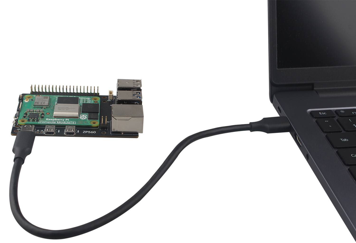
Switch the Boot switch to the ON position to enter flashing mode.
Please refer to the link below to operate:
https://www.raspberrypi.com/documentation/computers/compute-module.html#flash-compute-module-emmc
After flashing is complete, switch the Boot switch to the 1 position to deactivate flashing mode.
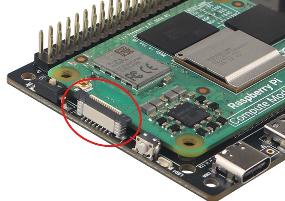
MIPI Interface
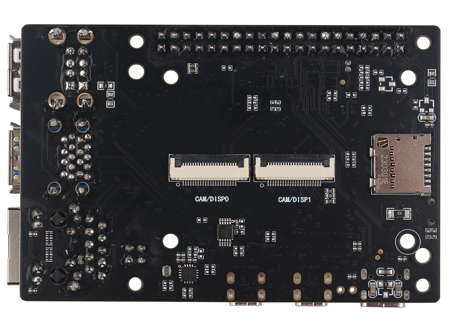
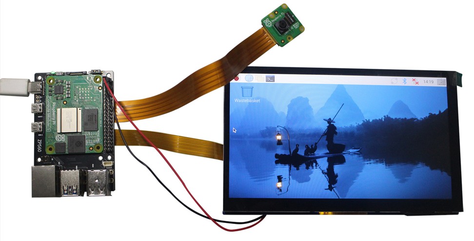
There are two MIPI interfaces, which can connect with camera and display.
Add the appropriate directive to /boot/firmware/config.txt to manually configure the driver for your camera model:
| camera model | directive |
|
OV5647 |
dtoverlay=ov5647,cam0 or dtoverlay=ov5647,cam1 |
|
IMX219 |
dtoverlay=imx219,cam0 or dtoverlay=imx219,cam1 |
|
IMX708 |
dtoverlay=imx708,cam0 or dtoverlay=imx708,cam1 |
|
IMX477 |
dtoverlay=imx477,cam0 or dtoverlay=imx477,cam1 |
|
IMX296 |
dtoverlay=imx296,cam0 or dtoverlay=imx296,cam1 |
|
OV9281 |
dtoverlay=ov9281,cam0 or dtoverlay=ov9281,cam1 |
|
IMX378 |
dtoverlay=imx378,cam0 or dtoverlay=imx378,cam1 |
Connect a display to DISPI0 or DISP1, add
dtoverlay=vc4-kms-dsi-7inch,dsi0
or
dtoverlay=vc4-kms-dsi-7inch,dsi1
to /boot/firmware/config.txt.
Reboot your Compute Module with sudo reboot. Your device should detect and begin displaying output to your display.
Execute the following command to verify if the camera is properly connected:
rpicam-hello -t 10s
Packing List
• 1 x ZP560 IO Carrier Board (Not include CM5)
Support
If you have any question or need technical support, please contact: support@zde.plus.